Science & Technology - 2017
October
SLOS: Newest Fast Camera in the West
HAPLS Featured in Optics & Photonics News
LLNL’s Optical Fibers Contribute to New Undersea Communications Technology
The Laboratory’s groundbreaking fiber optics program was featured in two high-level conferences with top Defense Department (DoD) officials earlier this year. Presentations at the conferences highlighted the Lab’s contributions to developing sophisticated underwater communications networks for national defense.
Scientists in the NIF & Photon Science Directorate have worked with the Defense Advanced Research Projects Agency (DARPA) and U.S. Navy laboratories on the Tactical Undersea Network Architectures, or TUNA, initiative. The program leverages unique, small-diameter, lightweight fiber optic cable to facilitate communications at sea.
Officials call TUNA “a novel, optical-fiber-based technology to temporarily restore radio frequency tactical data networks in a contested environment via an undersea optical fiber backbone.”
NIF&PS Fiber Laser Group Leader Mike Messerly presented a summary of LLNL’s work on fiber optic cable work for TUNA at the conferences. The conferences were the National Defense Industrial Association (NDIA) 2017 Joint Undersea Warfare Technology Spring Conference and the 2017 Johns Hopkins University Applied Physics Laboratory (JHU/APL) Submarine Technology Symposium.
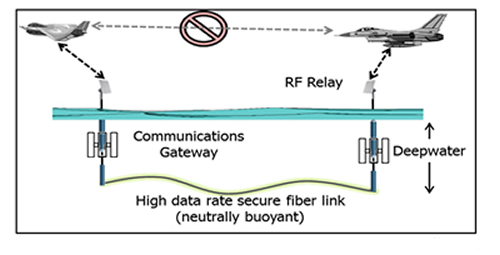
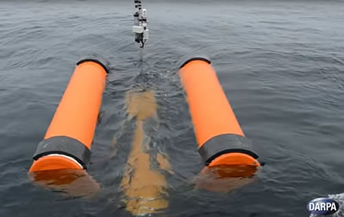
The TUNA program centers on the concept of deploying radio-networked buoys that would be linked undersea with neutrally-buoyant optical fibers—ultrathin hollow fibers that would neither float nor sink, but lie at a predetermined depth to avoid damage from fishing vessels and snagging on the ocean floor. The technology has captured much public interest, including articles in popular science magazines and a video DARPA posted highlighting completion of Phase 1 of the program:
The Fiber Laser Group’s challenge is to close the loop on the essential science involved in keeping the optics in a neutrally buoyant condition in a variety of ocean conditions and depths to maintain communications. In the event of a communications disruption, the TUNA buoys, each carrying communications equipment built to survive until communications can be restored, would be deployed at sea, then interconnected with optical fibers. The concept exploration phase of the TUNA program is complete and the program is now entering a demonstration phase, which includes at-sea testing.
“DARPA’s TUNA program has allowed us to expand and refine our fiber fabrication capabilities, and provided an opportunity to work with two Navy labs in California,” said Messerly. He noted that the two conference presentations have been ideal venues for meeting officials who are planning future Navy applications and missions and discussing how LLNL’s fishing line-like neutrally buoyant fibers might fit into or support them.
The NDIA Joint Undersea Warfare Technology event, held April 24-26 in San Diego with senior Navy leadership, was hailed by conference organizers as “one of the few opportunities industry has to learn about what is working and what is not working in undersea warfare technology, what the Navy needs help with, and how and when industry may contribute to future initiatives.”
Among the California sessions held was one on “Combat Systems/Warfighter Performance for DARPA’s TUNA Program, Enabling the Rapid Reconstitution of Tactical Data Networks in Contested Environments.”
The second conference featuring LLNL fiber-optics participation was held in May at the Johns Hopkins Applied Physics Laboratory in Maryland.

One day during the three-day JHU/APL Submarine Technology Symposium focused on “Effects Ashore: Precision Navigation in a GPS Challenged/Denied Ashore Environment,” and included a session on “Extremely thin neutrally buoyant optical fiber for multikilometer undersea communications.”
The JHU/APL conference was capped by a roundtable discussion with Navy leadership, including Vice Adm. Joseph Tofalo, Commander of Navy Submarine Forces; Rear Adm. Fritz Roegge, Commander Submarine Force, U.S. Pacific Fleet; Rear Adm. Bill Merz, Director, Undersea Warfare Division (CNO-N97); Rear Adm. Moises DelToro III, Deputy Commander for Undersea Warfare, Naval Sea Systems Command; and George Drakeley III, Executive Director, Program Executive Officer, Submarines.
These conferences are an example of the NIF&PS fiber optics program continuing its expansion, enabled by the addition of a unique fiber draw tower that allows custom design of high-purity fiber optics. Earlier this year the program launched new partnerships with the DoD’s High Energy Laser Joint Technology Office in research and development programs that include the MIT Lincoln Laboratory.
SLOS: Newest Fast Camera in the West
A multi-organization partnership has developed a new ultrafast diagnostic called the single-line-of-sight, or SLOS, camera that brings a 60-fold increase in full-frame shutter-speed capability to the National Ignition Facility. Researchers are hailing the new high-speed imaging technology as a much-anticipated breakthrough for high energy density and inertial confinement fusion (ICF) experiments.
LLNL led the SLOS camera development in collaboration with Sandia National Laboratories (SNL), San Diego-based General Atomics (GA), and UK-based Kentech Instruments Ltd. The new capabilities it brings to NIF include:
- Using advanced sensor technology for full-frame time sequencing of imaging for the first time; and
- Shutter speeds as short as 35 picoseconds (trillionths of a second).
 Joe Kilkenny, left, NIF scientific diagnostic leader, and Terry Hilsabeck of General Atomics examine the drift tube in NIF’s groundbreaking single-line-of-sight camera. The drift tube is analogous to the slow-motion feature on a standard camera. Credit: Kenneth Piston
 The new SLOS sensor introduces a burst-mode capability similar to a motor drive on a standard camera. It can take images in rapid-fire sequence with a two-nanosecond gate integration of time, said Arthur Carpenter, a NIF diagnostics engineer and the responsible system engineer for the SLOS camera. It then uses a “time microscope” to divide these time slices down by a factor of 60, resulting in gate widths of 35 picoseconds.
“This is a marvelous example of an international collaboration,” said NIF Scientific Diagnostic Leader Joe Kilkenny, a longtime leader in the effort to develop the SLOS and other next-generation imaging cameras.
The SLOS innovation merges two recent high-speed imaging technologies: the DIXI (dilation x-ray imager) currently used in NIF, and an advanced double-layer hybrid complementary metal oxide semiconductor sensor, or h-CMOS, developed by SNL. Equipped with the h-CMOS sensor, SLOS increases shutter speed by a factor of three over traditional framing cameras used in NIF.
Expectations are high for SLOS in the wake of the camera’s successful commissioning in September. It is expected to compliment DIXI, which is considered the world’s fastest two-dimensional x-ray framing camera. DIXI can capture images of NIF implosions at 200 billion frames a second, but it can’t record images over the same area on the image plane multiple times.
Understanding Implosions
The advantage that SLOS brings is the ability to image NIF shots with full-frame time sequencing; researchers expect that capability to enable greater understanding of the implosions they record, Carpenter said. “The major limitation of microchannel-based framing cameras like DIXI and hGXD (the hardened gated x-ray detector) can be overcome with this system,” he said.
DIXI uses the centuries-old pinhole photography concept to generate an image. With the new SLOS sensor for NIF, Carpenter notes, researchers can now couple advanced x-ray optics technology that can focus images down to get significantly better spatial resolution with ultra-fast timing to sharpen clarity.
“With SLOS you can look at a sequence of full-frame images,” he said. “There’s been a lot of excitement in the community about this technology.”
The SLOS technology is considered a transformational diagnostic under the National Nuclear Security Administration’s 2016 Inertial Confinement Fusion Program Framework.
SLOS also offers some radiation resistance, with the capability of handling medium-yield shots. Development of the SLOS camera electronics also allowed real-world testing of radiation-hardening techniques for the next generation SLOS system currently under development, Carpenter said.
Armed with its sophisticated sensors, SLOS will provide two full frames per shot; a planned upgrade in 2018 is expected to allow SLOS to capture four frames per shot. With the next-generation version on NIF, the SLOS 2, researchers plan to gain 16 frames on a radiation-hardened version of the camera built to handle high-yield shots.
“SLOS 2 might have the first small-scale active electronics that will operate during a high-yield shot inside the Target Chamber,” Carpenter said.
 Members of the research team that designed and engineered the SLOS camera (center) prepare it for installation on NIF. From left: Arthur Carpenter, Matthew Dayton, and Kenneth Piston of LLNL, Terry Hilsabeck of General Atomics, and Sabrina Nagel of LLNL. Credit: Jaebum Park
 At the inaugural commissioning experiment on Sept. 21—the 400th NIF shot in Fiscal Year 2017—a crowd of researchers from NIF and General Atomics gathered to watch the successful fielding of the dilation-aided diagnostic. The experiment was led by Carpenter and LLNL physicist Sabrina Nagel, who served as principal scientist for DIXI and worked on the development of the SLOS diagnostic.
“We have data!” Nagel called out when the shot went off at 7:30 p.m., and immediately dove into analyzing the data. She describes the pulse-dilation process as similar to pacing cars coming off a highway ramp and onto the freeway. Stop-and-go lights accelerate the autos along the highway, placing fast cars out front and slower cars in the rear so they don’t bunch together. After some time on the freeway their spacing will increase; in the same way, pulse dilation allows a relatively slow detector to pick out a set of electrons, leading to a faster effective shutter speed.
With that increased control of the SLOS, Nagel said, comes the ability to get more images from a single line of sight recorded per shot of the laser—like a camera being able to take more photographs of the same scene.
“You can think of it as getting more frames with your camera,” she said. “Instead of one frame or a bunch of frames but with blurred images, you can get four all spaced out evenly.”
 Data from the Sept. 21 SLOS commissioning experiment. Gate width for the shot was 100 picoseconds and the inter-frame time was 195 picoseconds. Credit: Sabrina Nagel
 The other advantage of the SLOS system is the “gates,” or timing limitations between frames (snapshots), are flexible; depending on the experiment, researchers can control the time between images—an impressive amount of control considering the time-gate measurements are in trillionths of a second.
A Marriage Made in Heaven
“This will for the first time give you actually improved temporal resolution of these single line-of-sight CMOS detectors because we have the dilation part in front,” Nagel said. “Now we will have multiple images, from a real single line-of-sight image, with a 40-picosecond temporal resolution from any x-ray source you want to image.”
Kilkenny highlighted the importance of the SLOS technology to ICF research: “A true single-line-of-sight camera is enabled by a marriage made in heaven between the pulse-dilation technology, which Sabrina has demonstrated on NIF, with the 10-to-20 picosecond gate time of DIXI and the ability to record four gated images with nanosecond gating with hybridized CMOS focal plane arrays.”
One of the developers of both the DIXI and the SLOS fast cameras is Terry Hilsabeck of GA. He noted that when DIXI, using pinhole imaging, was unable to achieve the higher spatial resolution the researchers sought, the collaborating team pursued the method of capturing more frames from one image on a single line of sight, allowing the use of higher-performance x-ray optics.
Hilsabeck worked on the problem with scientists from Sandia, GA, Kentech and Livermore. The collaboration faced technical challenges in trying to develop a way to use a digital chip to record and store enough images of a laser shot in a series, or time sequence. The burst-mode h-CMOS sensors were developed to achieve nanosecond-scale, multi-frame image recording by storing data locally in pixels during the event, so it could hold multiple images in sequence. The physics of signal propagation on the chip, however, limit the gate speed to about a nanosecond—too slow for time-resolved core imaging.
The h-CMOS sensor has 160 electrical connections that must penetrate the vacuum barrier of the electron tube. The sensor’s photodiode array originally was designed to detect visible light and 6 keV (6,000 electron-volt) x-rays. Detecting electrons would require tripling the electron energy in the tube. The team needed to develop adequate radio-frequency shielding, because the photocathode at the input end of the SLOS instrument is excited at the kilovolt level, while the sensor—which sits only 50 centimeters away—is recording millivolts.
“The biggest risk we had,” Hilsabeck noted, “was that in that tube, you’re pulsing kilovolts on one end and you’re sensing millivolts on the other. That’s a million times stronger, so you worry about noise, and the question was whether that sensor would work in that ‘noise’ environment. So we put up enough shielding around it and it ended up working well.”
What does this new SLOS diagnostic ultimately bring to NIF? “If we get better data quality,” Hilsabeck said, “then we get more understanding of how the implosions are performing—and hopefully that will lead to higher yields. That’s the goal.”
HAPLS Featured in Optics & Photonics News
The LLNL-developed High-Repetition-Rate Advanced Petawatt Laser System (HAPLS) once again graces the cover of a scientific research publication.

HAPLS is the cover feature story in the October issue of Optics & Photonics News, published by the Optical Society of America (OSA). It also was highlighted in the July/August issue of the Laboratory’s Science & Technology Review in an article titled, “Advanced Laser Promises Exciting Applications.”
In the Optics & Photonics News article, “High-Average-Power Ultrafast Lasers,” LLNL physicists Tom Spinka and Constantin Haefner, NIF & Photon Science program director for Advanced Photon Technologies, discuss the role of HAPLS in the context of a new generation of petawatt (quadrillion-watt) peak-power lasers.
“When tightly focused,” they wrote, “PW-peak-power lasers can generate intensities of greater than 1021 W/cm2 and electromagnetic fields more than 100 times stronger than the field that binds electrons to atomic nuclei. This opens a range of interesting and potentially useful laser–matter interactions.
“However,” they continue, “these lasers still have one weakness: a very low pulse repetition rate. Many of them fire only once every few minutes, and even the advanced PW laser at the Lawrence Berkeley National Laboratory’s Berkeley Lab Laser Accelerator facility fires only once per second.”
By contrast, HAPLS, which was designed and constructed by LLNL for the European Extreme Light Infrastructure (ELI) Beamlines project, “is poised to increase the repetition rate of PW-peak-power laser pulses by an order of magnitude.” HAPLS is designed to deliver petawatt laser pulses with energy of at least 30 joules and durations less than 30 femtoseconds (quadrillionths of a second) at a repetition rate of 10 Hz (10 times a second).
 The ELI–Beamlines facility shunts output from four laser beamlines on the ground floor to six experimental halls in the basement. HAPLS, to be known as the L3 laser system and expected to be the “workhorse” of the facility, was delivered to ELI Beamlines in June. Credit: ELI Beamlines
 “At ELI Beamlines,” the authors write, “the ability of new lasers to produce extreme intensities on targets—in multiple pulses per second—should drive forward new discoveries in high-intensity laser science and transform laser-driven particle and radiation sources from scientific curiosities into viable tools.”
HAPLS is currently being integrated into the ELI Beamlines facility, which is expected to be ready for use by the international scientific community in 2018.


