Chamber Geometry
This page summarizes the conventions used in describing the placement of NIF beams, target inserters, diagnostics, and other equipment on the target chamber.
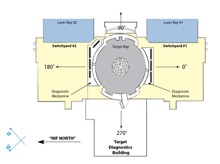
Figure 1 shows the general layout of the western end of the NIF building, including the target area, the two laser bays and switchyards, and the diagnostic building.
The NIF laser consists of 192 beamlines, grouped as follows:
- 4 beamlines in a quad (numbered 1-4 for "Top" quads, 5-8 for "Bottom" quads)
- 2 quads in a bundle (labeled T (top) and B (bottom))
- 6 bundles in a cluster (numbered 1-6)
- 2 clusters in each laser bay (numbered 1, 2, and 3, 4)
- 2 laser bays in the facility (numbered 1, 2)
In the switchyards, each individual bundle is divided into two quads, one each for the upper and lower hemispheres of the chamber. Laser beams enter the chamber at the quad level; that is, the target chamber contains 48 individual laser beam ports (24 in the upper hemisphere, 24 in the lower) with 4 beams passing through each. The quad is the basic independent unit for experiments.
The quads are named with the cluster and bundle number and a suffix that indicates whether the quad is the top (T) or bottom (B) quad in the bundle, as Q13T or Q45B. Each quad is mapped to a single port on the target chamber. All top quads enter through ports on the top half of the chamber, and all bottom quads enter through ports on the bottom half of the chamber.
The NIF target chamber is arranged with a vertical z-axis. The quads enter the target chamber through ports that are located on 4 cones at 23.5°, 30°, 44.5°, and 50° polar angles. The NIF beams are oriented to support indirect-drive hohlraum experiments with the hohlraum mounted vertically (Fig. 2). For ignition or other experiments requiring a highly uniform implosion, separate inner and outer beam cones are available to allow time-dependent control of drive symmetry. The inner and outer beam cones are produced by the (23.5°, 30°) and (44.5°, 50°) beams, respectively.
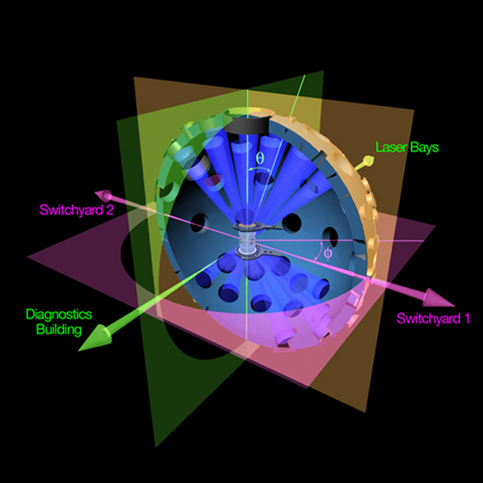
Ports in the NIF target chamber are identified in spherical coordinates using the convention shown in Fig. 2. The elevation angle θ is measured from vertical, and the azimuthal angle Φ in the horizontal plane is measured counterclockwise from the axis running from target chamber center through the center of Switchyard 1.
For further information on scientific opportunities at the NIF, please contact:
User Office
PHONE: (925) 422-2179
nifuseroffice@llnl.gov


