Science & Technology - 2017
January
UCOP Grant Will Fund New High Energy Density Science Center
A Clearer Look at NIF Fusion Implosions
It’s a basic fact about photography: the higher the resolution, the clearer the image.
The same holds true for the super-sophisticated diagnostic equipment that scientists use to examine the results of NIF fusion experiments. Only instead of determining resolution by the number of megapixels as in a camera, the resolution of advanced NIF diagnostics is measured in microns, or millionths of a meter (a human hair is about 60 microns wide).
An example is the Kirkpatrick-Baez Optic (KBO) x-ray microscope, a unique diagnostic with a one-meter-long telescoping extension that allows the magnifications needed to study fusion implosions on NIF (see “Promising New X-Ray Microscope Poses Logistics Challenges”). The new diagnostic provides less than eight-micron resolution imaging and improved signal strength in collecting x-ray light when compared to similar imaging systems currently used on NIF.
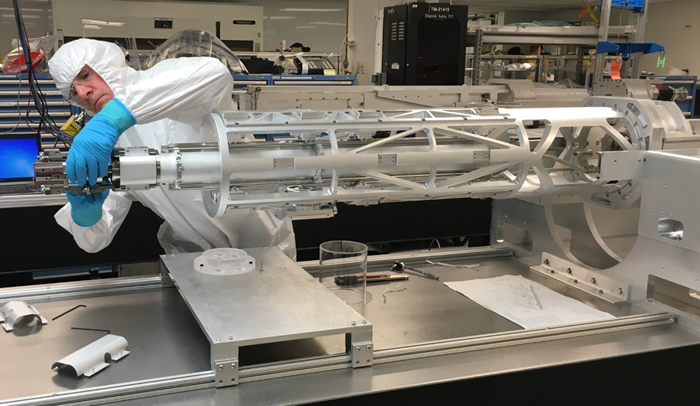 Engineer Tom Mccarville installs a mirror pack on the second-generation KBO diagnostic. Four pairs of precisely aligned mirrors make up four x-ray imaging channels to capture a NIF implosion as it evolves.
 “What’s nice about using the Kirkpatrick-Baez microscope is that it has very high resolution but it’s also energy-sensitive,” said physicist Louisa Pickworth. When used to obtain images of the tiny “hot spot” at the center of a NIF target capsule during an implosion, the KBO “has great spatial resolution, and it also has the ability to look in a narrow energy band with good signal. It’s very difficult to achieve that combination when imaging the hotspot,” she said.
First demonstrated in 2015, the KBO recently was upgraded to a second-generation model that’s been “hardened” so it can be used in NIF experiments that produce neutron radiation without the detector being damaged. In a fusion experiment last fall, the diagnostic produced the clearest images yet of the effects on NIF implosions caused by two engineering features—the ten-micron-diameter fill tube used to insert fuel into the target capsule, and the ultrathin “tents” that suspend the capsule inside the hohlraum (see “How NIF Targets Work”).
Previous studies have indicated that both the fill tube and the tents cause perturbations in NIF implosions that interfere with the hot spot’s ability to generate the energy needed to spark a self-sustaining fusion reaction that results in ignition. That has led to a search for alternate ways to inject fuel into the capsule and to hold it inside the hohlraum.
In the experiment, researchers placed a layer of high-density carbon (HDC) “doped” with a small amount of tungsten on the inner surface of the HDC target capsule. When the capsule imploded, the tungsten-doped layer emitted bright x-rays that clearly showed the perturbations, or “jets,” from the fill tube and tents early in the hot-spot burn.
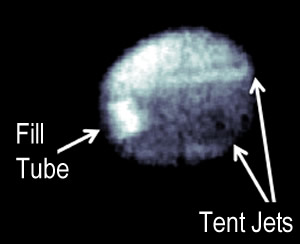 A KBO image from the tungsten-emission experiment. The image, captured at 190 picoseconds (trillionths of a second) before “bang time,” highlights the perturbations caused by the fill tube and the tents.
 “The tungsten on the inner surface ‘lights up’ as the hot spot is forming,” Pickworth said. “When the tungsten gets hot it’s going to glow, and glow really brightly; this gives us a snapshot of the inner surface of the shell and any perturbations.
“About 300 picoseconds before what we call bang time, which is the peak emission from the implosion, you begin to see a really bright dot on a very low background circle; that bright dot is the fill-tube perturbation. When we directly compare this to 2D simulations, it’s wider than we expect it to be, but it is showing up at about the same time as we would expect it to.
“So this suggests,” she said, “that the perturbation that’s being caused by the fill tube is not quite what we would expect simply from a tube going into the capsule—that maybe there’s something more going on there.”
The KBO images also confirmed the presence of perturbations caused by the tents. “We expected that the tent feature is there, but it’s difficult to visualize,” Pickworth said. “So this is a nice image of the effect of the tent. We’re getting the high resolution and that energy sensitivity that we wanted from the KBO.”
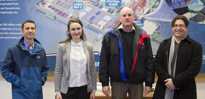 KBO diagnostic team members (from left) Justin Buscho, Louisa Pickworth, Tom Mccarville, and Jay Ayers. Credit: Jason Laurea
 Pickworth gave credit to the engineering team led by KBO System Manager Jay Ayers for upgrading the KBO so it could be used in high-neutron-yield experiments. The upgrade also included adding pinholes to the KBO diagnostic that can send x-rays to NIF’s Dilation X-ray Imager (DIXI), the world’s fastest x-ray framing camera, to provide a time history of ignition implosions along with the high-resolution energy-bounded images from the KBO. DIXI records a frame every five picoseconds, the equivalent of 200 billion images a second.
As for the KBO, “our vision for this year is to run it on lots of experiments and to really get everyone to see what its potential is, to see that they can do some really awesome science with it,” Pickworth said. “For example, this experiment revealed many things that we weren’t expecting.”
Joining Pickworth for the tungsten-emission experiment were researchers Harry Robey, Vladimir Smalyuk and Bruce Hammel. Along with Ayers, key members of the team responsible for the KBO upgrade were engineers Tom Mccarville and Justin Buscho. Tom Pardini, Julia Vogel, and Stefan Hau-Riege of the Physics and Life Sciences Directorate made significant contributions to the development of the multilayer substrates in the mirror pack. Inspector Greg Pons of the Engineering Directorate performed precision alignment using a coordinate measuring machine.
Tiny Mirrors Hold Big Promise
You can’t use them to put on makeup or shave—they’re much too small—but an array of up to 10,000 tiny “micromirrors” under development at LLNL could be one of the next big things in optics, lasers, and miniaturization.
The mirrors, only one millimeter on a side—about the width of a pencil tip—could become key players in technologies ranging from laser communications and 3D displays to autonomous vehicles and directed energy. They also eventually could help improve beam wavefronts coming off the meter-scale mirrors used in ultra-powerful laser systems like NIF, enabling significant performance improvements.
 Micromirror arrays could reduce the size and cost of bulky LIDAR (Light Detection and Ranging) units, like the one on top of this self-driving car being tested.
 LLNL’s digital micromirror array (MMA)—thousands of microscopic mirrors that can move up and down like pistons and tip and tilt like see-saws—has the potential to create or significantly enhance many high-performance optics, imaging, detection, communications, and manufacturing technologies. The technology features a repeating pattern of microscale devices, each of which controls a miniature mirror.
“This technology excels at controlling and directing light,” said LLNL engineer Bob Panas, principal investigator for the Light-field Directing Array, or LDA, program. “Our micromirror array promises faster, more accurate motion and larger range of motion than what is currently on the market.”
Initially funded by LLNL’s Laboratory Directed Research and Development Exploratory Research (LDRD-ER) program, the new MMA has unique features that “allow us to boost the range-speed product between 10 and 100 times greater than previous arrays,” Panas said. “They can go much faster at ranges of motion that people care about.”
“Together these operate like a single large mirror, with the benefit of fast and fine motion control,” he said. “The elements in the array are capable of tip, tilt, and piston motions. That allows us to point the light in any desired direction as well as control the phase of the light exiting the array to maintain high-quality beams.”
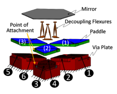 Exploded diagram of a single micromirror and its actuating devices.
 The new design will enable advanced applications in areas such as 3D image projection, manufacturing, and high-speed focusable LIDAR. LIDAR, which stands for Light Detection and Ranging, is a remote sensing method that uses light in the form of a pulsed laser to measure variable distances; it’s a key technology in the current push for self-driving vehicles.
“This is one of the first micromirror arrays with integrated closed-loop control,” Panas said. “We have sensors built into the mirrors that allow us to sense where it is in terms of its rotation and motion, and we can use this for real-time feedback to compensate for any unwanted motion in the device. This provides the ability to lock the device to the performance you want—even in a noisy, vibration-rich environment like a moving vehicle. We want to be able to operate in a real-world environment.
“The mirrors are independently controlled, so we can adjust the focal distance of the array,” Panas noted, “and a 99 percent fill factor allows us to handle high-intensity beams without damaging the array (fill factor is the ratio of light-sensitive area of a pixel to total pixel area in an image sensor).
“The mirrors are ‘array-able’ over large areas,” he added. “We envision this being operated upwards of 10,000 element arrays over about 10-by-10-centimeter surfaces. Each element is capable of moving over large mechanical ranges, upwards of 80 degrees optical range, or being designed for very fast speeds—upwards of 80 kHz of fine-motion bandwidth.”
The micromirrors and their actuating devices are fabricated through a combination of microfabrication and additive manufacturing techniques, with several unique and patented features incorporated in their design. For example, the array can be split to send out beams in different directions to map large areas in parallel. It also can focus in on an object of interest—a person, a vehicle, or a building—to obtain a finer mapping of a particular area.
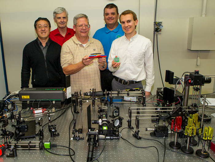 Micromirror team members (from left) Andrew Cao, Steve Hunter, Tim Uphaus, Chris Harvey, and Bob Panas show off their micro-electro-mechanical systems (MEMS) hardware, developed from initial LDRD investments. The team is standing in LLNL’s laser additive manufacturing laboratory, where key microscale parts are printed out for use in the MEMS micromirrors. MEMS devices and structures consist of miniaturized mechanical and electro-mechanical elements made using microfabrication techniques. Credit: Jason Laurea
 “This is not possible with existing devices,” Panas said, “most of which use oscillatory or rotary mirrors that can’t be focused in on objects of interest. The ability to control the light field emanating from the array allows us to send out different images in different directions so we can achieve glasses-free, multi-axis 3d image projection.”
Another potential application is video-rate confocal microscopy, where the mirrors are used in a microscope to scan over small objects like cells to produce 3D images. “The speed of our array enables this to be done at video rate so we can watch motions and changes occur,” Panas said. “And the high bandwidth of the mirror array as well as its high accuracy allows us to do image stabilization for uses like maintaining laser communications between moving vehicles.
“Finally,” he added, “the large area of the array combined with its high fill factor makes it possible for us to direct high-energy beams without damaging the array. This enables a wide range of new applications in power transfer, additive manufacturing, 3D printing, and a whole range of new laser manufacturing technologies and defense applications.”
The LDA program has sparked interest from several industry sponsors, as well as the Department of Defense, prompting further development of the technology for laser communications and other applications. The closed-loop control of the array provides a means to reject disturbances between platforms, including atmospheric turbulence, machine vibration, and maneuvering. This enables precision optical tracking in active environments.
Another area for further development is high-energy beam steering; NIF’s operators have expressed interest in a mature, large-scale light-field directing array for high-energy beam control.
Participating along with Panas in developing the technology were LLNL’s Andrew Cao, Julie Jackson, Will Smith, Tim Uphaus, Phil Paul, Maxim Shusteff, and Steve Hunter, in collaboration with Professor Jonathan Hopkins of UCLA and Carolyn White of AMFitzgerald, a microfabrication consulting firm. The Laboratory’s Chris Harvey, Jay Dawson, and Mike Carter also supported the effort.
UCOP Grant Will Fund New High Energy Density Science Center
The University of California Office of the President (UCOP) has awarded $4.1 million over three years to Professor Farhat Beg of UC San Diego, in partnership with physicist Frank Graziani of LLNL, to create a multi-campus Center for Frontiers in High Energy Density Science.

The new research center will study the fundamentals of nuclear physics, planetary science, and astrophysics. The field of high energy density science examines material properties and physical processes under extreme conditions of temperature and pressure, such as those that exist in the interiors of stars and during inertial confinement fusion experiments at facilities like NIF. Other participants are from UC Berkeley, UC Davis, UCLA, UC Santa Cruz, and Los Alamos National Laboratory (LANL).
Beg is principal investigator for UC San Diego’s High Energy Density Physics Group. The UC center will integrate with LLNL’s Center for High Energy Density Science with the goal of having students, postdoctoral researchers, and faculty come to LLNL to use Department of Energy (DOE) facilities and develop technical collaborations.
“The project will enable transformative research and technical development,” said LLNL lead investigator Graziani, “by partnering UC campuses with DOE partners by novel use of DOE facilities, unique research and technical collaborations between UC and DOE scientists, and by deepening connections between theory, experiment, computation, and applications.”
The grant is one of four grants and four graduate fellowships totaling more than $14 million to enable UC researchers to collaborate with staff scientists at LLNL and LANL. UC scientists received a total of $7.9 million to work with LLNL researchers on two research grants and two in-residence graduate fellowships. The awards are part of the UC National Laboratory Fees Research Program aimed at enhancing UC collaborations on biological applications of advanced computing, high energy density science, and mesoscale materials science.


