Science & Technology - 2016
June
A Top-down View of NIF Neutron Emissions
Getting Laser Diodes to March in Lockstep
Laser diodes are compact and efficient electronic devices used in compact disc players, laser printers, remote controls, and many other consumer products. Grouping several laser diodes into an array can produce enough power to energize, or “pump,” a high-energy solid-state laser source with much greater efficiency than, for example, the giant flashlamps that energize the NIF lasers.
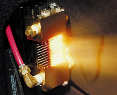 An LLNL laser diode array developed in the early 1990s. Recent optical conditioning technologies could lead to substantial improvements in beam quality in these arrays.
 By themselves, however, laser diode arrays normally can’t be used as high-energy laser sources because they typically consist of many independent and incoherent apertures, or “bars,” that produce low-beam-quality radiation with limited brightness or radiance. But that could change if the bars could be optically coupled and phase-locked so they produce coherent light (where the crests and troughs of the light waves are all in lockstep).
As used today, high-average-power diode arrays usually consist of diode bars that have 10 to 25 independent broad-area facets, or emitters, spaced along the length of each bar, with individual facets emitting incoherently with respect to each other.
“In the past, phased arrays had a lot of problems,”” said LLNL researcher Sheldon Wu, the principal investigator for a Laboratory Directed Research and Development (LDRD) project aimed at increasing both the spatial and spectral brightness of laser diode arrays. “One is the‘smile’ problem, which is a bend in the crystal structure of the diode bar so the laser emitters don’t line up. This could be from stress or from imperfections in the material, and it makes it difficult to feed back light from one emitter into the others.”
Another issue limiting phase locking, Wu said, is the tendency of the independent emitters to operate at slightly different center wavelengths. This wavelength variation is caused primarily by emitter-to-emitter differences in the local operating environments.
To overcome these challenges, the three-year LDRD project is taking advantage of recent advances in optical conditioning technologies. They include the availability of customized micro-optics to correct aberrations in the individual apertures, and highly spectrally selective partial reflectors in the form of volume Bragg gratings (VBGs).
“We want to impose a fixed phase relationship between the lasers (in an array),” Wu said. “If the emitted light is the same wavelength and has a fixed spatiotemporal relationship, it’s perfectly coherent. This would be an ideal wavefront, and the laser array would focus to a much tighter spot with much higher radiance on the target.”
The higher beam quality would improve laser diodes used as pumped sources, and also could allow the use of direct diodes in many applications that now require diode-pumped systems—including systems for defense, supporting the Laboratory’s national security mission, and materials processing. Wu said the team is making “good progress” on demonstrating phase locking between facets in individual bars, and researchers are now designing experiments using multi-bar and kilowatt-class, two-dimensional arrays to be conducted in Fiscal Year 2017.
The project’s ultimate goal is a “convincing demonstration of phase-locked laser-diode arrays in a robust and simple package to usefully bring such devices into the repertoire of the directed-energy and photonic-assisted materials processing communities.”
Joining Wu on the project are LLNL colleagues Ray Beach, Mike Johnson, Bill Molander, Frank Ravizza, and Mark Rotter.
A Top-down View of NIF Neutron Emissions
A new diagnostic built on NIF’s roof is giving researchers a clearer picture of the neutrons released during laser-driven implosions of target capsules containing deuterium or deuterium and tritium (DT).
Instruments inside the North Pole neutron Time of Flight (nTOF) enclosure, a structure slightly larger than an industrial shipping container, detect and record neutron arrival times, providing researchers with much-needed data in the northern hemisphere of the NIF Target Chamber.
“It will give us a view of what we’ve been missing, and we believe a quieter one (with less interference) than what we’ve gotten so far,” said NIF Co-Target Diagnostic Manager Mark Jackson.
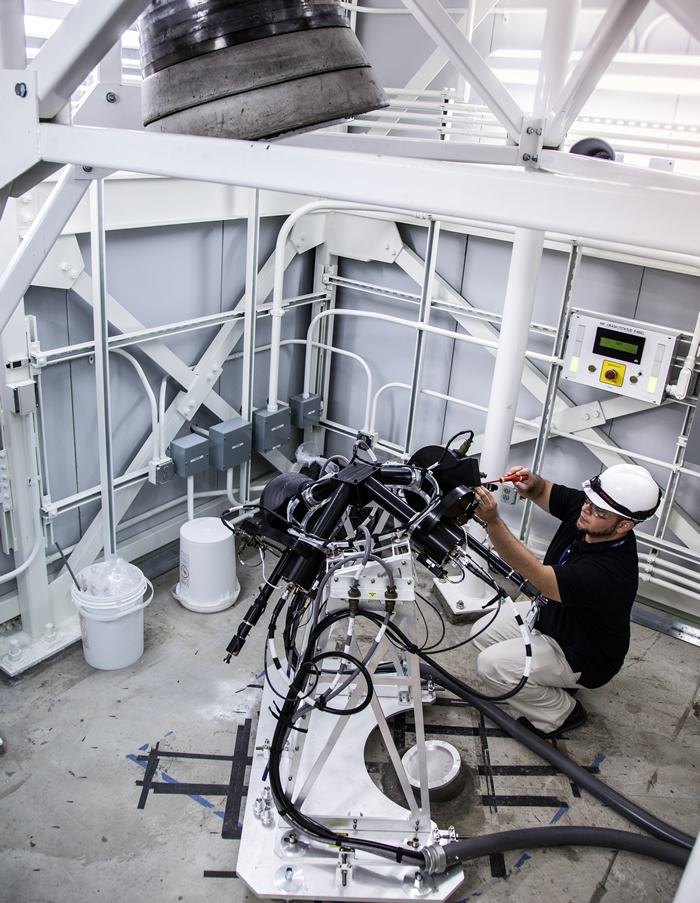 Target Diagnostics engineer Francisco Barbosa completes installation of the North Pole nTOF diagnostic on the roof of the NIF building. The round aluminum disk at the bottom of the diagnostic is the last of several collimators carrying the diagnostic beam. The concrete cone above the diagnostic is the beam dump, which prevents radiation from leaving the NIF site.
 The north pole system joins four other nTOF detectors—one located in the basement of the Target Bay (south pole), two on the Target Chamber equator, and one in the neutron alcove. The new nTOF is on the roof to provide a view of neutrons almost directly opposite from the south pole detector, enabling researchers to determine if the neutron source is moving coherently.
“The detectors in the nTOF measure the time of flight of the thermonuclear neutrons from the implosion to the detector, and so their velocity,” said Joe Kilkenny, chief NIF experimentalist for measurements. “The north pole nTOF is close to opposite to NIF’s south pole nTOF. Importantly, this allows the Doppler shift of the neutrons due to motion of the compressed plasma—like the pitch of a train’s whistle changing as it approaches you and moves away from you—to be measured from the difference in the arrival times at the north and the south pole nTOFs.”
As neutrons produced in the Target Chamber pass through the bibenzyl crystal housed in the North Pole nTOF enclosure, they induce scintillation light. The crystal’s scintillation light is collected by a fast photo-detector which in turn produces a voltage in proportion to the number of passing neutrons. This voltage signal is then digitized every 100 picoseconds (a tenth of a billionth of a second), producing a high-fidelity record of the neutron flux passing through the detector.
The data collected by the devices will help researchers determine the shot’s yield, as well as interesting properties of the plasma producing the neutrons, including its temperature and velocity. Understanding those properties motivated constructing the north pole system opposite the existing south pole system.
Construction crews began work on the enclosure last fall, cutting a 40-foot by 20-foot hole in the top of the NIF building down to the inner concrete ceiling of the facility. The precise alignment and the tricky angle of the three-inch-diameter line-of-sight flight path from Target Chamber center (TCC), projecting through a small hole in the floor of the structure, required an impressive feat of engineering. It also presented challenges from wind and seismic load, facility modification, and temperature control, Jackson said. About 30 LLNL employees worked on the project over the last year, about half of them from the Lab’s engineering staff.
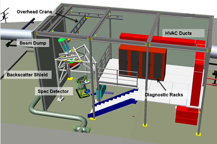 Illustrations of the North Pole nTOF and its enclosure. The red line in the figures below shows the flight path, or line of sight (LOS), of neutrons as they pass from the Target Chamber to the scintillator in the nTOF enclosure. The LOS path is defined by a set of precision collimators. A concrete and steel block behind the scintillators and a concrete and tungsten beam dump above the diagnostic prevent radiation from traveling outside the facility.
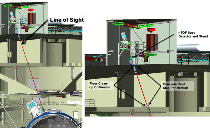
Behind the scintillators in the nTOF enclosure, preventing the neutrons from traveling further upward and outside the enclosure, is a three-foot thick concrete and steel block. The block is capable of fully stopping neutrons and photons, ensuring that any emissions are within the facility’s safety limits and reducing the risk of outside radiation exposure to a negligible level.
The line-of-sight path is defined by a set of precision collimators that allow researchers to look at only the neutrons coming from the area around TCC.
To allow for more efficient operation, and to minimize the time NIF employees will have to be on the roof, the detector can be operated by remote control.
Not only is the newest detector a technological improvement over the others, said Perry Bell, NIF Co-Target Diagnostics Manager, but the line of sight it affords is the best yet for researchers because there is limited mass around it to interfere with the measurement.
NIF has more than 70 diagnostics in all, and Bell said two more diagnostics similar to the North Pole nTOF will be built to extend the facility’s diagnostic reach even further.
“These detectors will provide additional insight into fusion ignition and will represent key diagnostics for the NIF program,” Bell added.
The U.S. Department of Energy funded the construction and design of the diagnostic.
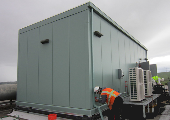 Workers put the final touches on the North Pole nTOF enclosure on the Target Bay roof.


