Science & Technology - 2014
December
Guiding Intense Laser Pulses Through Thin Air
LLNL’s fiber draw tower, a state-of-the-art facility for fabricating specialized fiber optics, is being put to one of its sternest tests yet: producing complex multichannel fibers with ultrathin webbing and tiny filaments a few billionths of a meter thick.
The 8.2-meter-tall fiber draw tower was commissioned in February 2012 to provide the Laboratory with the capability of producing optical fiber structures for a wide variety of research projects. Since then, the NIF & Photon Science Fiber Group has been working on ways to overcome the inherent power limitations of conventional silica fibers, including developing ribbon-shaped photonic crystal fibers (PCFs) that increase the surface area for heat removal, thus extending the thermal limit for power scaling.
The latest project, funded by the Laboratory Directed Research and Development (LDRD) Program, is developing a new approach to hollow-core fiber (HCF) technology, in which the laser light is primarily guided in the air in the empty core instead of by solid fiber material.
In a hollow-core PCF, tiny and closely spaced air holes running the length of the fiber act as reflectors to confine the light in the empty core. Using a hollow-core fiber testbed, European scientists and engineers recently achieved the world’s highest data transmission rate of 57.6 terabytes per second—50 times faster than the previous record.
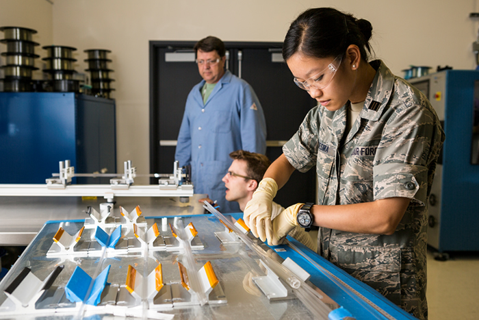 NIF&PS Summer Scholar Celine Ledesma (right), Reggie Drachenberg (kneeling), and Nick Schenkel work on hollow-core fibers in the fiber draw tower lab.
 “In conventional fiber lasers, the light is guided by total internal reflection,” said LLNL researcher Mike Messerly. “In the hollow-core fibers it’s guided by a constructive interference phenomenon. The great advantage of these fibers is that the breakdown thresholds for air are much higher than for glass. The light intensity is not limited by damage in the glass, so it can transport more energetic pulses or higher-power laser beams.”
The idea for hollow-core lasers originated in the United Kingdom, at Bath and Southampton universities, a little more than a decade ago. Along with their use in data transmission and precision measurement systems, hollow-core fibers are being studied for potential application in optical sensing, especially chemical and biological sensing. Filling the hollow cores of the fibers with liquid or gas enables direct interaction between the propagating light and the material being analyzed, enhancing the sensitivity of the sensors.
“You get a long interaction length,” Messerly said, “because the fiber guides a highly focused spot, so the beam can be very intense and can interact intensely with a gas over a long length. The gas might be a sample from the environment, and you could be looking for traces of certain chemicals.” The fibers already have been used to detect low levels of CO2, biomedically significant molecules such as glucose, and bacteria.
Another potential application is laser-based particle accelerators. Jay Dawson, who leads the Fiber Group, said traditional accelerators based on radio-frequency technology “would be scaled down to optical wavelengths by taking a hollow-core optical fiber and shooting light into it to make an accelerator.” Dawson said the Department of Energy and scientists at SLAC National Accelerator Laboratory and Lawrence Berkeley National Laboratory have expressed interest in the application of lasers to accelerators.
Hollow-core fibers, however, can have substantially higher propagation losses than solid-core fibers. The LLNL project is working to mitigate those losses by developing “negative curvature” HCFs, in which the core boundary has a convex shape when seen from the center of the fiber.
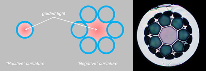 LLNL’s latest negative-curvature fiber (right) has provided the first indication of hollow-core guiding. The glass webbing separating the capillaries is about the thickness of the wavelength of visible light (550 nanometers).
 “It’s now widely accepted that negative curvature is the key to low loss,” Messerly said. “However, it’s difficult to fabricate. We need to fabricate thin webs of glass on the order of a wavelength thick. The challenge is to control the thickness as you draw the glass out of the (draw tower) furnace.”
To shape the negative curvature structure, different pressures have to be applied to the core and the cladding during the fiber drawing process. “A difference of one-tenth of a pound per square inch can be the difference between too little and too much pressure,” Messerly said. “We need to control the pressures to half that, or .05 psi.”
To brush up on current practices, the Fiber Group’s Reggie Drachenberg attended a recent University of Bath fabrication workshop, which covered techniques for applying differential pressures, drawing large capillaries, and “snuggly” stacking filaments to avoid water contamination.
“The big fabrication challenge is controlling the pressure and making the fibers reproducible, and that’s where we are now,” Messerly said. “It’s a matter of mastering the process.”
Joining Messerly, Dawson, and Drachenberg on the project are LLNL researchers Paul Pax and Nick Schenkel. NIF&PS Summer Scholar Celine Ledesma, who has returned to school, also participated.
Measuring NIF’s Enormous Shocks
NIF experiments generate enormous pressures—many millions of atmospheres—in a short time: just a few billionths of a second. When a pressure source of this type is applied to any material, the pressure wave in the material will quickly evolve into a shock front. One of NIF’s most versatile and frequently-used diagnostics, the Velocity Interferometer System for Any Reflector (VISAR), is used to measure these shocks, providing vital information for future experiment design and calibration.
Invented in the 1970s, VISAR was developed by Sandia National Laboratory scientists to study the motion of samples driven by shocks and other kinds of dynamic pressure loading. It has since become a standard measurement tool in many areas where dynamic pressure loading is applied to materials.
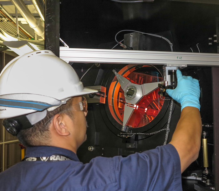 Target Area Operator Mike Visaya aligns a VISAR transport mirror in preparation for an experiment.
 “It is a big challenge to figure out how to apply these enormous pressures without immediately forming a shock wave,’ said Peter Celliers, responsible scientist for VISAR. “Instead of trying to avoid forming shocks, many NIF experiments use a sequence of increasing shocks as a convenient way of monitoring the performance of the target as the pressure drive is increased—for example, during a (target) capsule implosion.”
To measure these shocks, VISAR determines the speed of a moving object by measuring the Doppler shift in a reflected light beam. More specifically, it directs a temporally-coherent laser beam at the object, collects a returned reflection, and sends it through a specially-configured interferometer. The interferometer produces an interference pattern containing information about the Doppler shift.
The Doppler shift provides information on how fast the reflecting part of the target is moving. In most cases the reflector is a shock front, which acts like a mirror moving through a transparent material (for example liquid deuterium, quartz or fused silica). In some cases the moving mirror is a physical surface on the back part of a package (called a free surface) that is accelerated during the experiment. In yet other scenarios the moving mirror could be a reflecting interface embedded in the target behind a transparent window.
After the light reflected from the target passes through the interferometers, it forms a fringe pattern. With the NIF VISAR design, this light is collected in the form of a two-dimensional image with an optical image relay system. The fringe pattern is superimposed on the image, then projected on the slit of a streak camera. Because the target image is spatially-resolved across the slit of the streak camera, this type of VISAR is called a line-imaging VISAR. The spatial and temporal arrangement of the fringe pattern in the output streak record reveals how different parts of the target move during the experiment.
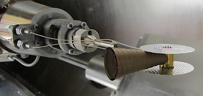 (Above) At the end of a NIF target positioner, a foam target package is mounted on the side of a hohlraum inside the large VISAR shielding cone. (Below) Illustration of a VISAR cone installed in a target capsule and typical dual-channel VISAR interferometry data.
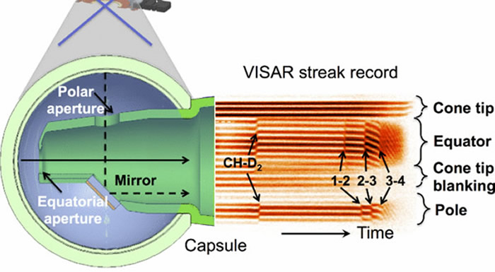
There is a very close connection between the velocities of the moving parts of the target and the pressure driving the motion. If the velocity is measured accurately, a highly accurate picture of the driving pressure can be formed. This information is vital for understanding the details of target performance. “Our simulation models are not accurate enough to calculate the timing of the shocks that produces the best performance without some sort of calibration,” Celliers said. “But by monitoring the shocks with the VISAR, we have precise and detailed information that can be used to tune the laser pulse (the pressure drive) to achieve optimal target performance, and to calibrate the simulation codes.”
Looking to the future, VISAR will see improvements to its streaked optical pyrometer (SOP), an instrument that can be used to infer the temperature of a hot object by measuring the heat radiated from the object in the form of visible light. The SOP is undergoing modifications to improve its imaging performance and to reduce background levels on the streak camera detectors. This will benefit future equation-of-state experiments where accurate thermal emission data is crucial. This upgrade will be complete in early 2015.
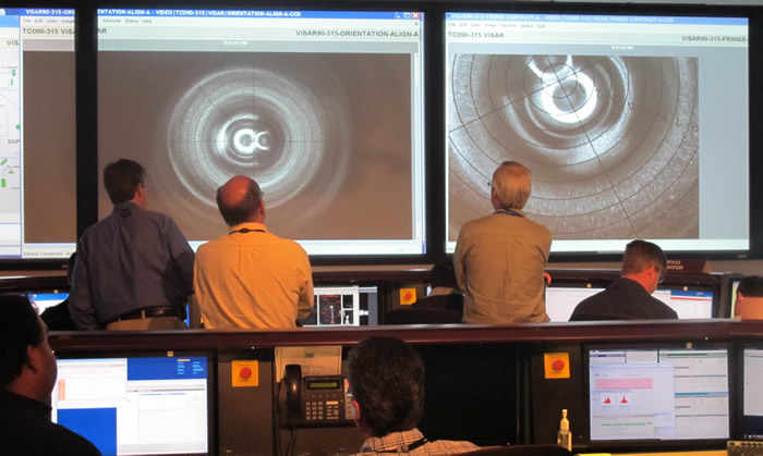 Physicists Dave Farley (left) and Peter Celliers and layering scientist Curtis Walter watch a live VISAR image as they monitor the deuterium fill of a keyhole capsule in the NIF Control Room during shock-timing experiments.
 Along with Celliers, the VISAR implementation team includes Stephen Azevedo, David Barker, Jeff Baron, Mark Bowers, Aaron Busby, Allen Casey, John Celeste, Hema Chandrasekaran, Kim Christensen, Philip Datte, Jon Eggert, Gene Frieders, Brad Golick, Robin Hibbard, Matthew Hutton, John Jackson , Dan Kalantar, Kenn Knittel, Kerry Krauter, Brandi Lechleiter, Tony Lee, Brendan Lyon, Brian MacGowan, Stacie Manuel, JoAnn Matone, Marius Millot, Jason Neumann, Ed Ng, Brian Pepmeier, Karl Pletcher, Lynn Seppala, Ray Smith, Zack Sober, Doug Speck, Bill Thompson, Gene Vergel de Dios, Abbie Warrick, Phil Watts, Eric Wen, Ziad Zeid and colleagues from National Security Technologies.


