Papers and Presentations - 2016
July
NIF Experiment Challenges Standard Ionization Models
Measuring Instabilities in NIF Implosions at Peak Velocity
‘Contact Lenses’ for High-power Lasers
Could Capsule ‘Shims’ Enhance NIF Implosions?
Sometimes a carpenter’s best friend is a shim—a narrow, wedge-shaped piece of wood or plastic that can be used to close a gap when components are out of plumb or don’t quite fit together.
LLNL researchers are looking into a similar technique to try to close the gap between the expected performance of NIF implosions, in terms of neutron yield or energy produced, and the results of experiments to date. In a Physics of Plasmas paper published online on July 22, the researchers described the results of computer simulations indicating that “shimming,” or slightly altering the dimensions of NIF target capsules, has the potential to significantly improve implosion performance and neutron yield.
The simulations indicate that shimming could compensate for implosion issues caused by radiation asymmetry— the unequal distribution of the x-ray flux in a NIF hohlraum that drives the implosions. “We believe the radiation asymmetry from the hohlraum is a significant source of degradation” in an inertial confinement fusion (ICF) experiment, said LLNL physicist Dan Clark, lead author of the paper. “Simulations show it has an order of magnitude impact on the neutron yield.”
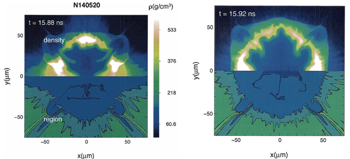 Images showing the results of two-dimensional post-shot simulations of a 2014 NIF experiment. The images show the imploded deuterium-tritium (DT) fuel at the time of peak neutron production. The symmetry axis is horizontal, and the upper half plane shows the material density, while the lower half plane shows the material region. Dark and light blue correspond to the regions that were initially DT gas and DT ice, and the green regions show the various doped ablator layers. A large low-mode (long-wavelength) asymmetry, driven by asymmetries in the hohlraum radiation field, is evident in the left image. These long-wavelength asymmetries have been largely removed in the image on the right by applying the appropriate capsule shim.
 Large, long-wavelength implosion perturbations driven by these asymmetries in the hohlraum radiation field, along with a large perturbation seeded by the ultrathin “tent” that suspends the target capsule in the hohlraum—which is amplified by ablation-front hydrodynamic instability growth—are thought to be the chief factors responsible for the current shortfall in NIF’s neutron yield.
While efforts are under way to develop modified hohlraum designs with reduced asymmetry imprint, “hohlraum physics is incredibly complicated,” Clark said. “So let’s also try to work on the capsule to offset some of the issues the hohlraum is creating.”
In the Physics of Plasmas paper, the researchers report on two-dimensional radiation hydrodynamics simulations of two recent NIF implosion experiments. The results suggest that deliberately misshaping, or shimming, the capsules “could be highly effective at counteracting current asymmetries and result in factors of a few enhancements in neutron yields. For higher compression designs, the yield improvement could be even greater,” they said.
“These are very, very small changes in the shell,” Clark noted. “We’re talking about a millimeter-size capsule with a two-micron perturbation on the outside—you wouldn’t be able to see it with the naked eye. The simulations indicate that with the shims you can nearly cancel the asymmetry that we believe the hohlraum is imposing on the implosion.”
NIF researchers currently are looking for ways to eliminate the use of the tents by testing a variety of alternative methods to support the capsule in the hohlraum. “If the perturbation from the tent can also be mitigated by developing some other, less perturbing support mechanism,” said the authors, “then the simulations suggest that order of magnitude improvements in yields may be possible when shims are used.” While the results are based only on simulations, they are interesting enough to start considering experiments to test this method for asymmetry control on NIF.
Shims should not be looked to as the solution to the problem of hohlraum asymmetries, the researchers added, but as part of a possible larger solution. If shims can be shown to work, they said, shims could be combined with other techniques to expand the hohlraum design space for symmetry implosions within NIF’s energy envelope.
Clark was joined on the paper by LLNL colleagues Chris Weber, Vladimir Smalyuk, Harry Robey, Annie Kritcher, Jose Milovich, and Jay Salmonson.
NIF Experiment Challenges Standard Ionization Models
When hydrogen fuel is compressed to extreme densities and temperatures in NIF inertial confinement fusion (ICF) implosions, a very dense plasma—a chaotic mixture of freely moving ions and unbound, or free, electrons—is created. Researchers need to understand the properties of this material in order to design successful ignition experiments, as well as to model the state and evolution of planets and dwarf stars.
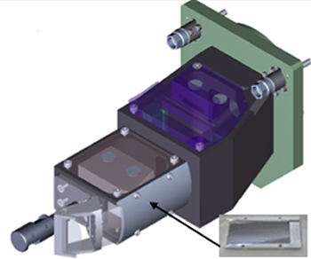
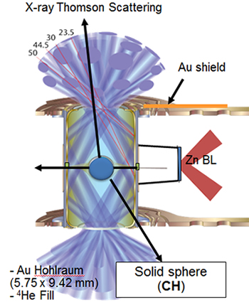 (Above) Experimental setup for the GigaBar EOS Discovery Science experiment. A standard inertial confinement fusion (ICF) gold (Au) hohlraum with a near-vacuum gas fill was irradiated by 176 laser beams delivering a total energy of 1.1 megajoules and a peak power of 425 terawatts. The resulting radiation field drove a spherical implosion of a solid polystyrene (CH) sphere in the center of the hohlraum. Nine-keV (9,000-electron-volt) backlighter (BL) x-rays emitted from helium-like zinc were scattered off the compressed sample and collected by a high-efficiency crystal spectrometer (below) through the upper laser entrance hole.
A recent Discovery Science experiment on NIF, however, indicates that widely used models describing the ionization balance in a hot dense plasma—the number of bound compared to unbound electrons—underestimate the amount of ionization that occurs when material is subjected to the kinds of pressures and temperatures created by converging shocks driven by NIF’s laser beams.
The experiment, reported in a Physical Review E paper published online on July 21, used 176 laser beams to create pressures exceeding 100 megabars (100 million atmospheres) in a solid polystyrene (plastic, or CH) sphere. The sample ionization state was measured by NIF’s new x-ray Thomson scattering (XRTS) platform (see “Measuring Ionization at Extreme Densities”) using ~9-keV (about 9,000-electron-volt) x rays produced by a zinc backlighter foil located 7.5 millimeters from the center of the CH sphere and irradiated by an additional 16 laser beams. The experiment approached the conditions needed to dislodge the electrons closest to the nucleus, known as K-shell electrons, from their orbits.
“We can see from these results that the current ionization model is off at high pressures,” said LLNL physicist Tilo Döppner, a member of the experimental team. “The experiment shows higher ionization in CH than the common model would predict. This is important, because many thermodynamic quantities depend on the ionization state of the material.”
The findings are of special significance for ICF experiments, Döppner said, because knocking electrons from the innermost atomic shells reduces the absorption of the plastic ablator, and that can cause errors in radiographic measurements of the remaining mass of imploding ICF capsules.
The experiment was performed as part of the GigaBar Equation of State (EOS) campaign of the NIF Discovery Science program. Döppner said the development of the XRTS platform, including the construction of a new high-efficiency gated spectrometer, required “a lot of hard and dedicated work by a large number of people. X-ray Thomson scattering is a challenging diagnostic technique,” he said, “but this new NIF data point (for ionization balance measurements) has already triggered new theoretical work in dense plasma physics.”
Future experiments will drive hollow CH capsules to even higher compression, pressures approaching one gigabar (one billion atmospheres), and electron densities of 1025 per cubic centimeter. “This is a very interesting plasma state because of its high degree of degeneracy and correlations,” Döppner said, “potentially with sufficient energy density to fully ionize carbon—and it’s only possible at NIF.”
Former UC Berkeley postdoc Dominik Kraus, who worked on the experiment at NIF, was lead author of the paper. He and Döppner were joined by LLNL researchers Annie Kritcher, Benjamin Bachmann, Rip Collins, Dan Kalantar, Nino Landen, Tammy Ma, Sebastien Le Pape, Joe Nilsen, and Damien Swift and by collaborators from the University of Warwick and the Atomic Weapons Establishment in the UK, SLAC National Accelerator Laboratory, Washington State University, and the GSI Helmholtz Center for Heavy Ion Research in Darmstadt, Germany.
Measuring Instabilities in NIF Implosions at Peak Velocity
One of the most important challenges to achieving ignition at NIF is understanding and controlling the instabilities that cause target capsule shell material to mix with fusion fuel during inertial confinement fusion (ICF) implosions. In a Physical Review Letters paper published online on July 11, LLNL researchers and their colleagues reported on a new experimental technique that has enabled the first measurements of the total hydrodynamic instability growth near the peak velocity of a NIF implosion (about 900,000 mph), after the initial acceleration phase is complete.
The research joins several other new experimental approaches developed for NIF with the goal of pinpointing the sources of hydrodynamic (fluid) instability growth and improving the capability to computationally model them.
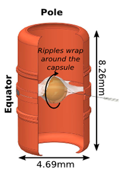 Cutaway diagram of the gold hohlraum used in the recent hydrodynamic growth experiments showing the pole, equator, and orientation of the ripples on the plastic ablator (capsule). Thin plastic membranes, or “tents,” hold the capsule inside the hohlraum.
 Even though a NIF implosion lasts only a few billionths of a second, it has two distinct phases, noted LLNL physicist Bruce Hammel. “It’s unstable as it accelerates in,” he said, “and it’s unstable as it decelerates.”
The first phase consists of a rocket-like acceleration as the hohlraum x-ray drive ablates, or blows off, target capsule material and accelerates the capsule and fusion fuel inward. This is followed by a rapid deceleration when the shock front “rebounds” from the target’s center and moves back through the capsule in the opposite direction, slowing the implosion.
“During the first phase the low-density ablated material is ‘pushing’ on the higher-density shell,” Hammel said. “This is an unstable process in which the low-density material bubbles through the high-density material to ‘get around it.’ In an ICF implosion, this means that bumps on the capsule surface and other imperfections are amplified as the implosion accelerates inward.
“During the second phase, the lower-density ‘hot spot’ in the center of the capsule pushes back against the denser shell and stops the implosion; this is also unstable,” he said. “The net result is that some of the shell material can mix with the fuel in the hot spot, cooling it and reducing the amount of fusion reactions that can occur.”
As in previous NIF hydrodynamic growth radiography (HGR) experiments, special target capsules with pre-imposed sinusoidal modulations, or “ripples,” on the capsule surface were used (see “Controlling Hydrodynamic Mixing in NIF Implosions”). The experiments measure the growth of hydrodynamic instabilities as a function of the frequency, or “mode” of the ripples (the number of ripples around the capsule). Unlike the previous HGR experiments, however, which were able to measure growth only part of the way through the acceleration phase, the new studies are the first to measure the state of the shell at the end of the acceleration phase, when the implosion has reached peak velocity.
“There are two unknowns in terms of how perturbed the shell is when it implodes,” Hammel said. “One unknown is the growth factors—how much does a ripple get amplified, and what is that amplification factor as a function of the frequency of the ripples, or mode number. The other unknown is what is the state of the capsule when you start. What are the initial perturbations that get amplified by the growth factors?
“We carefully measure the capsules after fabrication with metrology, but there are still uncertainties, including the surface roughness,” he said. “We wanted to understand how perturbed the shell is when it finishes that acceleration phase so we can get a snapshot of how much the ripples or, ultimately, the inherent roughness on a shell, have grown once that first phase is completed.”
Along with measuring the growth of perturbations that arise from imperfections in the capsule’s surface, the research also is aimed at capturing the extent of instability growth caused by factors like the fill tubes used to introduce fuel into the capsule, and the ultrathin diaphragms called “tents” that suspend the capsule inside the hohlraum. “We really want to characterize the entire experiment,” said LLNL physicist Louisa Pickworth, who performed and analyzed the experiments and was principal author of the Physical Review Letters paper. “That’s what this (experimental) platform is for. It is one of the merits of this platform.”
To get a snapshot of the state of the implosion at peak velocity, the researchers employed a novel technique designed by Hammel. They added a small amount of argon to the gas in the plastic capsule to enhance the x-ray emissions from the central hot plasma created during the shock rebound phase of the implosion. In a process called self-radiography, the x rays were used to radiograph perturbation growth from inside the shell, as opposed to the external backlighter/reentrant cone configuration used in the previous HGR experiments.
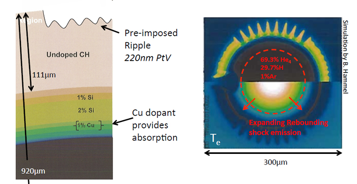 (Left) The plastic (CH) capsule was doped with silicon and copper. A mode 40 sinusoidal ripple was machined into the ablator with a 220±20-nanometer peak-to-valley (PtV) amplitude—the smallest amplitude possible using current fabrication methods—recessed three microns. (Right) 1 percent argon was added to the capsule’s gas fill to increase self-emission during the expanding, rebounding shock, forming a “self-radiograph.”
 The research measured perturbations at mode 40, which is at or near the peak of the growth factor curve for these implosions. “In contrast to previous experiments that measured hydrodynamic growth when the capsule was only partially imploded,” Hammel said, “these new experiments measured the total growth from the acceleration phase, when the capsule reached peak implosion velocity.”
By measuring the growth at peak velocity, the authors achieved the highest direct measurement of hydrodynamic growth in any ICF experiment to date—a factor of 7,000 amplification in areal density. Simultaneous measurements of the areal density growth factors at both the waist and pole of the capsule were an order of magnitude larger than previous HGR measurements, and differed by about a factor of two between the waist and the pole, showing asymmetry in the measured growth factors.
The researchers said the next step will be to take measurements during and at the end of the deceleration phase, when the target capsule is fully compressed. “It gets much harder to understand what happens in the capsule after the first phase is completed,” Hammel said, “because it gets even smaller by another factor of four or five, and the perturbations of interest are small enough in wavelength that you can’t resolve them with the instrumentation that we have.”
“The hot spot at peak compression in a layered implosion experiment is approximately 40 microns in diameter,” Pickworth added, “and the spatial resolution we have in the diagnostics we’re running at the moment is about 10 microns, so we can only achieve a small number of spatial resolution elements across that entire hot spot. We have been working hard to build new x-ray diagnostics which have better spatial resolution.”
Pickworth said higher-mode perturbations could soon be observed through the use of new high-resolution imaging systems, such as the Kirkpatrick-Baez (KB) microscope, recently demonstrated on NIF (see “Promising New X-Ray Microscope Poses Logistics Challenges”). The new diagnostic combines better than eight-micron-resolution imaging with narrow-band energy responsiveness in addition to a larger photon collection efficiency when compared to similar imaging systems at NIF. This diagnostic will improve the measurements discussed in the paper, allowing higher modes and lower amplitudes to be measured.
“The KBO has great spatial resolution for these sorts of small objects, and it also has the ability to look in a narrow energy band,” Pickworth said. “It’s difficult to do that on ICF implosions.”
Pickworth and Hammel were joined on the paper by LLNL colleagues Vladimir Smalyuk, Andy MacPhee, Howard Scott, Harry Robey, Nino Landen, Maria Alejandra Barrios, Marilyn Schneider, Tom Kohut, Dean Holunga, Curtis Walters, Ben Haid, and Matthew Dayton and by Sean Regan of the Laboratory for Laser Energetics at the University of Rochester and Martin Hoppe, Jr., of General Atomics.
‘Contact Lenses’ for High-power Lasers
Optical components in high-power laser systems, such as the High-Repetition-Rate Advanced Petawatt Laser System (HAPLS) now under development at LLNL, can be distorted by laser-generated heat—especially when, as with HAPLS, the lasers are firing up to ten times a second.  The cover of the July 1 issue of Applied Optics shows a transmitted wave front (TWF) attenuating cell fabricated at LLNL for use in measuring high-gradient MRF imprints on transmissive optics. The resulting wave front aberrations need to be compensated for to achieve full laser performance.
LLNL researchers have developed a way to manufacture high-gradient optical elements that can correct for these distortions. Using a process called deterministic magnetorheological finishing (MRF), the technique can polish ultraprecise corrective topographical structures onto optical surfaces. The new process, which also uses a novel wave front attenuating cell to enable more reliable measurement of gradients than is possible with conventional interferometry, is described in the cover article in the July 1 issue of Applied Optics.
LLNL has been developing advanced MRF tools and processes for more than a decade to fabricate and deploy high-performance laser-resistant optics and beam-conditioning optical components for use in NIF, the OMEGA Laser at the University of Rochester, HAPLS, and other high-power laser systems. MRF polishing also is used to repair damage sites on NIF optics so they can be returned to service. 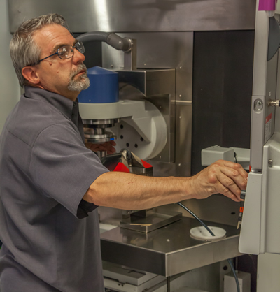 NIF & PS chemist Joe Menapace adjusts the Laboratory’s MRF machine in Bldg. 490. Credit: Clayton Dahlen
“MRF is a deterministic way of polishing optics,” said NIF & Photon Science Advanced Optical Finishing Group Leader Joe Menapace. “That means that if you know the state of the optic—its current condition, its curvature or wave front error—you can use a computer system and this tool to get it finished very rapidly, because you’re combining the computer system, interferometry, and your part.
“MRF uses a magnetizable fluid that interacts with a magnet and allows you to get a very, very high removal rate over a well-defined volume,” he said. “When the MRF tool is polishing an optic it will give preference to the high spots, if more material removal is needed, and ignore the low spots. The interferometry tells you what you have and where you want to go; the MRF does it quickly and with ultra-precision.”
In the Applied Optics paper, the researchers reported on the results of MRF imprinting a 23-micron-deep structure containing gradients over 1.6 microns per millimeter onto a fused-silica window that reflects the technique’s capabilities. The high-gradient element serves as a thermal correction plate for the HAPLS system, which will be a key element of the ELI-Beamlines facility, the world’s new preeminent, high-intensity laser science facility in the Czech Republic. HAPLS is designed to ultimately generate a peak power greater than one petawatt (one quadrillion watts), with each pulse delivering 30 joules of energy in less than 30 femtoseconds (trillionths of a second). The laser system will deliver the pulses of light at 10 Hertz (10 repetitions per second).
“Using this deterministic method of manufacturing corrective optical elements is a key enabling technology allowing us to push the frontiers of high average power laser systems,” said Constantin Haefner, program director for advanced photon technologies at LLNL. “The remarkably high gradient that Joe and his team achieved to imprint with high resolution is beyond the capability of deformable mirrors and allows us to correct the wave front deformations where they occur—as if the laser would wear prescription contact lenses.”
 An example of a static thermal correction plate prescription for the HAPLS laser system generated from measurement of one if its subsystems while under anticipated operating conditions. (a) Prescription transmitted wave front (TWF) for the static thermal correction plate; peak-to-valley: 10.391 microns. (b) The corresponding prescription surface structure, showing that MRF imprinting will have to remove about 22.8 microns of optical material, in this case fused silica, to fabricate the static corrector.
 Joining Menapace on the Applied Optics paper were LLNL colleagues Haefner, Paul Ehrmann, Andrew Bayramian, Amber Bullington, Jean-Michel Di Nicola, Jeffrey Jarboe, Christopher Marshall, Kathleen Schaffers, and Cal Smith.


