Papers and Presentations - 2015
February
Probing Energy Loss in High-Rep-Rate Lasers
Determining Structural Evolution under Pressure
Studying Effects of Target ‘Tents’ on NIF Implosions
New NIF Implosion Models Reduce Discrepancies
Diamond Capsules Produce Promising Results
Most NIF inertial confinement fusion (ICF) experiments to date have used plastic target capsules to contain the hydrogen fuel. When the plastic is heated by x-rays generated inside a NIF hohlraum, it ablates, or blows off, causing a rocket-like implosion that compresses and heats the fuel until fusion is achieved.
One possible alternative to plastic is high-density carbon (HDC), a nanocrystalline diamond that has a number of advantages over plastic. Because HDC has a higher density, the same initial outer diameter results in a thinner initial shell and a larger initial inner diameter. The thinner shell leads to less absolute inward motion during shock compression, which produces an ablation front at larger radius when the peak of the drive and acceleration begins.
This larger radius and therefore larger ablation surface area results in higher efficiency and more absorbed energy compared to plastic. This allows HDC designs to reach ignition with a higher adiabat (internal capsule energy) compared to plastic ignition designs, or to achieve higher gains for a similar adiabatic. The larger initial inner radius also leads to an increase in fuel and hot spot mass for the same initial fill density. HDC also can be polished to a much higher surface quality than plastic.
Possible disadvantages include solid or partial melting of the HDC during compression, which may provide microstructures that seed hydrodynamic instability growth; also, reduced ablation-front scale lengths could produce larger overall instability growth leading to a mixing of ablator material into the hot spot.
In an article in Physical Review E published online on Feb. 25, LLNL researchers reported on the results of NIF implosion experiments using HDC capsules with laser pulse energies of 1.3 megajoules and peak power reaching 360 terawatts.
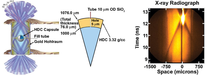 (Left) The target configuration for diamond (HDC) experiments on NIF. The hohlraum is 9.425 millimeters long and 5.75 mm in diameter. The 192 laser beams enter the hohlraum through two laser entrance holes 3.101 mm in diameter. The high-density carbon capsule is located at the center of the hohlraum and has a shell thickness of 76 microns. (Right) X-ray radiograph of the imploding HDC capsule. Late in time (top), the capsule self-emission dominates the recorded signal.
 Five indirect-drive ICF implosions were conducted with 76-micron-thick HDC capsules using a four-shock laser pulse optimized for HDC. The experiments demonstrated good laser-to-target coupling (about 90 percent) and excellent nuclear performance. A deuterium and tritium gas-filled HDC capsule implosion produced a neutron yield in excess of 1.6×10¹⁵ (1.6 quadrillion), approximately twice the yield of similarly filled plastic ablator capsules.
“These experiments confirm HDC as a viable material for ICF implosions and open the path for higher-velocity layered (cryogenic) implosions,” the researchers said. “Future experiments are planned with HDC capsules with the goal of reaching the alpha-heating regime, where alpha-particle deposition significantly enhances the neutron yield production, and eventually ignition.”
Lead author Steven Ross was joined on the paper by LLNL colleagues Darwin Ho, Jose Milovich, Tilo Döppner, James McNaney, Andrew MacPhee, Alex Hamza, Juergen Biener, Harry Robey, Eddie Dewald, Riccardo Tommasini, Laurent Divol, Sebastien Le Pape, Laura Berzak Hopkins, Peter Celliers, Nino Landen, Nathan Meezan, and Andy Mackinnon.
Probing Energy Loss in High-Rep-Rate Lasers
The next generation of high-energy lasers will operate at higher average power and higher repetition rates than current laser systems, and with lifetime spans of billions of shots. Such intense, long-term exposure to laser light can result in laser-induced damage to optical surfaces.
If damage precursors are present on the surface of the optics, repeated laser shots can cause various kinds of optical degradation, including transmission loss over time, buildup of contamination, development of photoluminescence, coating damage, and catastrophic laser damage (see “Keeping NIF Optics on the Job”). To better understand these effects, LLNL researchers have studied the impact of 351-nanometer (ultraviolet) laser light on fused silica surfaces for up to 109 (one billion) pulses with pulse fluences (energies) up to 12 joules per square centimeter.
In a recent article in Optics Express, the researchers reported that transmission loss from defect generation is a function of the pulse intensity and total integrated fluence, and is influenced by oxygen partial pressure, with the largest degradation occurring at low air pressures. In 10−6 Torr vacuum, at low pulse intensity, transmission loss increases monotonically as a function of number of pulses, the researchers said. As the pulse intensity increases above 13 megawatts per square centimeter, the observed transmission losses decrease, and are not measureable for 130 MW/cm2.
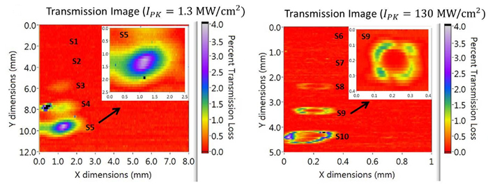 Transmission loss images for exposures on uncoated fused silica in vacuum (10−6 Torr) for (left) 1 mm beam with peak pulse intensity (IPK) = 1.3 MW/cm2 (pulse fluence (jp) = 0.12 J/cm2) and (right) 100 µm beam with IPK = 130 MW/cm2 (jp= 12 J/cm2). Inset shows magnified image. Color coding indicates the percent transmission loss relative to background (0% in red).
 “Absorption, not scattering, is the primary mechanism leading to transmission loss,” they said. “In 2.5 Torr air, no transmission loss was detected under any pulse intensity used…transmission loss is reduced when either the light intensity or the oxygen concentration is high. Based on these results, including a partial pressure of oxygen is the most desirable environment for silica optics in UV-based laser systems. Low pulse-intensity shots that lead to losses can be reversed by several methods including a buffered-oxide etch or laser-exposure in air.”
Lead author Sonny Ly was joined by LLNL colleagues Ted Laurence, Nan Shen, Bill Hollingsworth, Mary Norton, and Jeff Bude.
Determining Structural Evolution under Pressure
The study of material properties under the conditions of extreme high pressures and strain rates is important for understanding meteor, asteroid, and comet impacts, as well as in hypervelocity impact engineering, inertial confinement fusion (ICF) capsules, and basic high energy density (HED) physics. In a recent study published by Physical Review Letters, a team of LLNL scientists report a key finding that can be used to determine the evolution of structures under high pressure and strain rates.
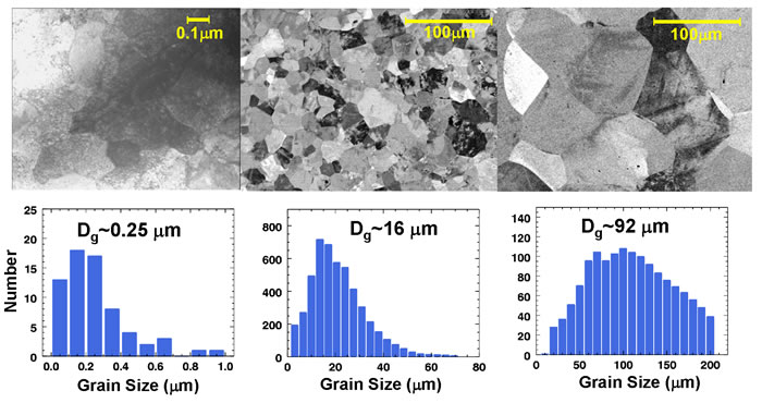
The paper details experimental results on the grain-size dependence of plastic flow stress (that is, resistance to plastic deformation) under high pressure (>100 GPa) and high strain rates (>107s-1). Higher flow stress means that the material is less prone to deform in the presence of an applied force. Under quasi-static conditions, smaller grain-sized materials are stronger. This observation is known as the Hall-Petch (H-P) relation and is used in industry to increase hardness, durability, and survivability of structural materials. It was not known, however, if the H-P relation holds under high pressure and high strain-rate conditions such as in hypervelocity impacts or ICF conditions.
 The experimental setup at the OMEGA Laser Facility, where the hohlraum drives the reservoir-gap configuration creating a ramped plasma drive that compresses and accelerates the sample without shock melting. The team measured the Rayleigh-Taylor instability driven ripple growth (deformation) to infer the dynamic flow stress of the tantalum (Ta) sample.
 “Measuring material flow stress at high pressures and strain rates without melting is a formidable task,” said lead author Hye-Sook Park. “We designed an experimental platform to drive tantalum samples to high pressures without melting using a laser-generated plasma piston drive.”
The strength of a sample material is inferred by obtaining a radiograph of the Rayleigh-Taylor (RT) instability-induced growth of ripples machined into the surface. Low-strength materials have little resistance to plastic (irreversible) deformation and the ripples grow rapidly due to the RT instability. In high-strength materials, ripple growth is suppressed. The measured amount of RT-induced ripple growth is used to infer the strength.
The team completed a series of experiments at the University of Rochester’s OMEGA Laser Facility. Measurements showed that flow stress is insensitive to grain size at the high strain rates of these laser experiments, whereas the H-P theory predicted an increase in strength of at least a factor of two under quasi-static conditions for these samples.
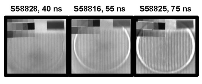 (Above) Face-on radiography images of Rayleigh-Taylor-induced ripple growth at different delay times. Higher-contrast patterns mean that the ripples have grown more. (Below) Electron microscope plan view images (top) of the samples used for the experiment. The grain size distributions (bottom) are shown for the Ta samples studied in these RT experiments.
“There are many surprises to be found in nature under the extreme conditions that we call the high energy density regime, and exploring material properties under these conditions has been challenging,” Park said. “Laser experiments provide a unique way for us to study this regime. The material dynamics under these HED conditions differ significantly from those under quasi-static conditions.”
The experiments studied materials at pressures of 100 GPa. Plans are now under way to extend the study to pressures of 500 GPa or higher at NIF and to include nano-grain samples (<30 nm in diameter) and samples including high pressure phase transitions. “We expect that many more exciting discoveries will emerge in this area in future experiments on OMEGA and NIF,” Park said.
Joining Park on the paper were LLNL colleagues Rob Rudd, Rob Cavallo, Nathan Barton, Tom Arsenlis, Jon Belof, Kerri Blobaum, Bassem El-dahser, Jeff Florando, Channing Huntington, Brian Maddox, Mark May, Chris Plechaty, Shon Prisbrey, Bruce Remington, Russ Wallace, Chris Wehrenberg, and Mike Wilson; Andrew Comley of the UK’s Atomic Weapons Establishment; Emilio Giraldez, Abbas Nikroo, Mike Farrell, and Greg Randall of General Atomics; and George “Rusty” Gray of Los Alamos National Laboratory.
Studying Effects of Target ‘Tents’ on NIF Implosions
A systematic study of the effects on NIF implosions of the ultra-thin mounting membranes that support target capsules inside NIF hohlraums was reported by LLNL researchers in a Physics of Plasmas paper published online on Feb. 4.
The performance of NIF’s inertial confinement fusion targets depends on the symmetric implosion of highly compressed fuel. The target capsule is held at the center of the hohlraum by two plastic membranes called tents. On early NIF shots, the tent membrane was 300 nanometers (nm) thick; as technology improved, targets were built with 110-nm, 45-nm, 30-nm, and most recently as thin as 12-nm tents (as the tent becomes thinner it becomes less reliable as a support.)
Because the mounting membranes are so thin, it was originally estimated that the tent would have acceptable impact on the implosion. The researchers found, however, that in low-adiabat (high-convergence) implosions, the tent seeds a perturbation at its lift-off position that leads to Rayleigh-Taylor hydrodynamic instabilities (RTIs) that can affect the symmetry and reduce the yield of NIF implosions.
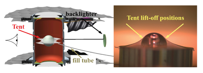 (Left) Illustration of the tent-mounted capsule inside the hohlraum in a backlit platform target. (Right) Image of the tent lifting off the capsule.
 The researchers used x-ray area-backlit imaging to assess in-flight low-mode (long-wavelength) 2D asymmetries of the shell. They said these time-resolved images reveal features that can be related to the lift-off position of the membranes. “Simulations with a tent-like feature normalized to match the feature seen in…backlit images predict a very large impact on the capsule performance from the tent feature,” they said.
The experimental data suggest that in the low-adiabat implosions, the tents seed RTIs at the capsule surface from the beginning, which grow throughout the implosion until they eventually come close to perforating the capsule. On the other hand, in higher-adiabat shots (shots with higher internal energy, making for lower density at the same pressure)—such as the recent, record-setting “high-foot” NIF experiments with higher initial laser pulses—the impact of the tent is significantly reduced due to the overall reduction of hydrodynamic instability in these implosions.
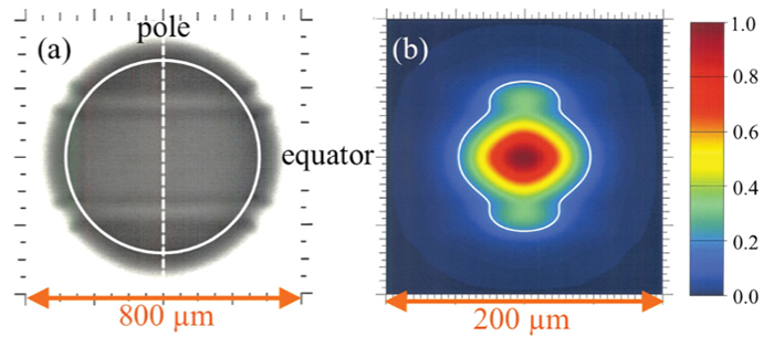 Simulated backlit (a) and core emission (b) images showing a feature that approximates the effect of a 45-nanometer tent.
 “Simulated high-adiabat implosions seeded with a similar (perturbation) do not show any visible feature in a radiograph image,” the researchers reported. “The tent feature is not predicted to have a significant effect on the performance of these high-adiabat implosions, consistent with their reduced hydrodynamic instability.
“This work shows,” they said, “that it is important to use mounting membranes that are as thin as possible, find mitigation strategies, for example, in the form of the laser pulse shapes for less instability growth, or alternative mounting strategies, and to keep this tent effect in mind when interpreting results of self-emission shape measurements.”
Lead author Sabrina Nagel was joined by LLNL colleagues Steve Haan, Ryan Rygg, Maria Alejandra Barrios, Robin Benedetti, Dave Bradley, John Field, Bruce Hammel, Nobuhiko Izumi, Oggie Jones, Shahab Firasat Khan, Tammy Ma, Arthur Pak, Riccardo Tommasini, Richard Pj Town, Chantel Aracne-Ruddle, and Michael Stadermann; K. Segraves of Schafer Corp.; and R. J. Strauser of General Atomics.
New NIF Implosion Models Reduce Discrepancies
New simulations that include recently identified effects which degrade the performance of NIF implosions have significantly narrowed the gap between modeling and experimental results, LLNL researchers reported in a Physics of Plasmas paper published online on Feb. 4.
The updated suite of one-dimensional (1-D), 2-D, and 3-D simulations include the current best understanding of effects identified since the National Ignition Campaign (NIC) concluded in September 2012. The effects could explain discrepancies between previous post-shot simulations of implosion performance and experimentally measured performance, particularly in neutron yield.
 Renderings of the DT ice-gas interface (a) and outer ablator surface (b) used as initial conditions for the 3-D HYDRA simulation of a NIF shot on March 21, 2012. In each, the color scale shows the deviation from the mean radius of the interface. Measured low mode and high mode surface finish data are incorporated in generating each surface. A large 3-D ice groove is apparent in (a), while the dark blue bands encircling the poles in (b) are due to the surrogate tent perturbation model.
 The new models were used to analyze a NIC experiment conducted on March 21, 2012—the highest compression shot yet fired on NIF and an important experiment for understanding the behavior of the high-compression implosions necessary to achieve ignition at the NIF energy scale. The updated simulations reduce the simulated-to-measured neutron yield ratio from 125:1 in 1-D to 1.5:1 in 3-D, as compared to 15:1 in the best 2-D simulations published previously.
Along with the experimental campaign conducted during NIC, a concerted effort was made to model NIC experiments in as much detail as possible using the HYDRA radiation hydrodynamics code. Across the full range of pulse shapes and target geometries explored during NIC, these detailed post-shot simulations consistently overpredicted implosion yields by factors ranging from three to 10. The discrepancy in yield was consistent and applied even in the case of state-of-the-art, high-resolution, 3-D simulations.
Subsequent NIF experiments have identified several important effects—absent in the previous simulations—that have the potential to resolve at least some of the large discrepancies between simulated and experimental yields. They include larger than anticipated low-mode (long-wavelength) distortions of the imploded core, due primarily to asymmetries in the x-ray flux incident on the capsule; larger than anticipated perturbations to the implosion caused by the thin plastic membrane or “tent” used to support the capsule in the hohlraum before the shot; and the presence, in some cases, of larger than expected amounts of ablator material mixed into the hot spot.
“Once these large effects are properly accounted for,” the researchers said, “the discrepancies found with previous simulations are largely resolved. While the agreement with the experimental data remains imperfect, comparison to the data is significantly improved and suggests that the largest sources for the previous discrepancies between simulation and experiment are now being included” in the models.
Lead author Dan Clark was joined on the paper by LLNL colleagues Marty Marinak, Chris Weber, Dave Eder, Steve Haan, Bruce Hammel, Denise Hinkel, Oggie Jones, Jose Milovich, Prav Patel, Harry Robey, Jay Salmonson, Scott Sepke, and Cliff Thomas.


