Efficiency Improvements - 2015
December
ATLAS Laser Tracking System Will Speed NIF Alignment
One of the most exacting and potentially time-consuming requirements for any NIF experiment is precisely aligning the diagnostics inside the Target Chamber so the results of the experiment will be correctly recorded. Until now, alignment of the facility’s diagnostic instrument manipulators (DIMs) has been handled by dedicated alignment systems known as the Opposed Port Alignment System (OPAS) and the Chamber Interior Viewing System (CIVS).
NIF currently has three DIMs—two positioned on the Target Chamber equator and one, the polar DIM, situated at the top of the chamber. Each equatorial DIM is positioned by an OPAS, a modified telescope located directly across the Target Chamber from the DIM. The polar DIM is positioned by the CIVS, a pair of video cameras positioned at a nearly 90-degree angle from each other to provide a three-dimensional view of the tip of the diagnostic, known as the “snout.”
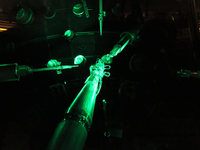
 NIF’s target and diagnostic positioners near Target Chamber Center. An equatorial DIM enters from the left and the polar DIM descends from the top of the chamber.
 In an effort to eliminate the need for installing a new dedicated alignment system whenever a new DIM is deployed, and to provide greater flexibility and save time during NIF shots, the NIF Team is in the process of commissioning an Advanced Tracking Laser Alignment System, or ATLAS.
“ATLAS will be able to see all of the existing positioners, DIMs and SXIs (static x-ray imagers) from one port,” said Nick Shingleton, the project’s responsible engineer. “So one of the benefits of ATLAS is it frees up some of those other ports; now we can put more diagnostics on NIF because we’re freeing up space, and space is expensive.”
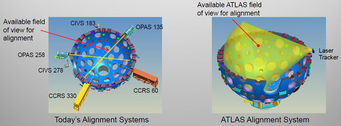
 Comparison of existing NIF diagnostic alignment systems with the Advanced Tracking Laser Alignment System (ATLAS). Also shown in the left graphic is the Chamber Center Reference System (CCRS), which provides a definition of the Target Chamber coordinate system. The CCRS views and provides feedback for the position and orientation of the Target Alignment Sensor (TAS) for each shot.
 A number of new diagnostics and target positioners are planned for NIF, including three combination DIM and target positioners known as target and diagnostic manipulators, or TANDMs. “If you aligned a TANDM the same way you aligned an equatorial DIM you’d need another OPAS,” Shingleton said, “so you’re taking up a whole other port. ATLAS can align those new positioners, so now they can add more TANDMs and just have the one alignment system that captures them all.”
The ATLAS laser tracker propagates collimated laser beams across the Target Chamber and uses optical systems to provide three-dimensional coordinate measurements. The tracker incorporates a servo system to steer the laser beam so that it tracks retroreflectors, known as corner cubes, on the DIM snouts. Low-power laser light reflects off the optical targets and back to the tracker; the returned signal is then analyzed for position to locate the retroreflecting target in 3D space.
Development of ATLAS was among the efficiency improvement projects recommended by last year’s “120-Day Study” mandated by Congress to increase NIF’s shot rate at a level funding rate. “The ATLAS project is one of the largest undertakings of the original 80 projects that comprised the 120-Day Study implementation plan,” said NIF Facility Manager Doug Larson. “It not only incorporated improving NIF’s efficiency and shot rate, it also provides additional flexibility for the shot directors in the sequence of alignment activities and improves the repeatability and accuracy with which instruments can be aligned in the polar DIM. The project touches many parts of the system including alignment, controls, safety interlocks, and operations. It has been a great success so far.”
One of ATLAS’ first jobs will be to take over the polar DIM alignment duties from CIVS, which was designed for collision avoidance and modified for alignment use. “When polar DIM was originally put in, there was nothing to align it, so the Target Area Alignment Group figured out how to use CIVS to partially do the job,” he said. “ATLAS will be able to do polar DIM alignment better than CIVS because it was engineered and designed to be a precision alignment system.”
The most demanding existing diagnostic on the polar DIM must be aligned to a tolerance of no more than 500 microns in order to acquire data. “We feel certain that with ATLAS we can get 500 microns with high confidence and high repeatability,” said NIF physicist Pascale Di Nicola. Along with the TANDMs, several other new diagnostic projects under development are planned to completely depend on ATLAS for alignment, including a polar neutron imaging system and an optical Thompson scattering diagnostic.
ATLAS provides flexibility during a NIF shot cycle by avoiding the need to look through the Target Chamber center (TCC) to view and align the DIM, which is not possible for OPAS when the target alignment system, or TAS, is deployed. “Because ATLAS doesn't look through TCC, there will be more flexibility in how you can sequence the shot,” Shingleton said. “If the DIMs offset (from TCC) were enough, you could align the DIM with ATLAS while TAS is aligning a target.”
“You also save a lot of time with the neutron mitigation,” added Di Nicola. “The cameras we use in OPAS are very high definition and they have very large field of view to get the resolution that we need. These cameras are very expensive, so when we’re doing a (high-neutron-yield) deuterium-tritium shot, we have to swap and swab the cameras in the middle of the shot cycle. And that takes time.” ATLAS was designed with this issue in mind and is easily removed and installed in the facility.
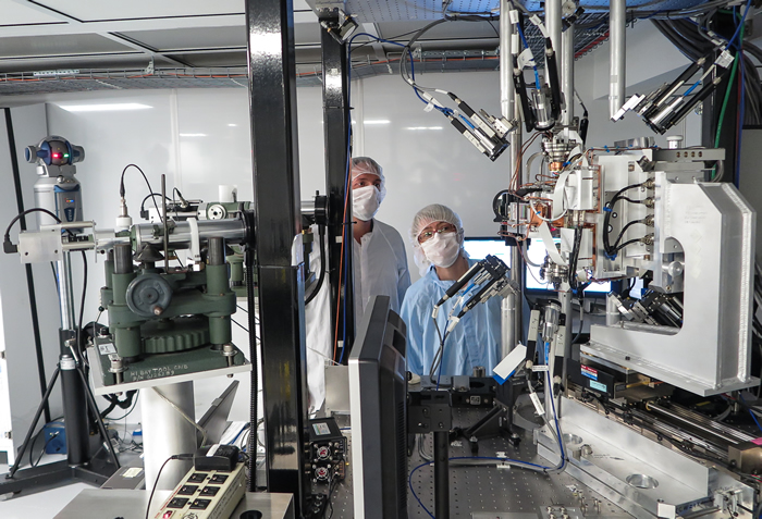
 In the NIF Operations Support Building, Integrated Computer Control System integration manager Rick Wilson and physicist Pascale Di Nicola prepare to utilize the new TAS4 target alignment system, which was modified to work with ATLAS, for a sequence of movements and measurements to characterize the accuracy of the laser tracker, shown on the far left. The TAS was moved to 50 different locations and the ATLAS measurements at each location were compared against the TAS to determine the tracker’s accuracy. Credit: James Pryatel
 Although the laser tracker was thoroughly tested and evaluated in a lab before it was mounted on the Target Chamber, additional testing will be required before it can be commissioned. “There is added complexity to ATLAS as a system,” Shingleton said. “The laser tracker measures points in space with the assumption that it’s propagating the laser through air. We’re propagating the laser through a vacuum window and into a vacuum (inside the Target Chamber) and that distorts the laser beam path as it goes through space. We have to apply a compensation for refraction in order to get those points that are measured back into real space so that we can use them for alignment.”
That compensation will be provided by the software now being developed to connect ATLAS with NIF’s Integrated Computer Control System (ICCS), which controls every aspect of a NIF shot. “A large part of ATLAS was the software development,” Shingleton said. “ICCS connects to the laser tracker to control it and collect the data. We embedded the refraction compensation into that code so that every time ATLAS takes a point measurement, ICCS applies that algorithm to correct the raw data.
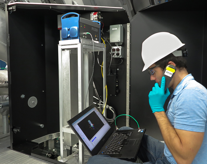
 ATLAS responsible engineer Nick Shingleton communicates with ICCS engineer James Hoffman while he controls movements of the ATLAS laser tracker during preliminary setting of coordinate baseline data. Credit: James Pryatel
 “The software development is critical for ATLAS to succeed as a system that can be used as an alignment tool for NIF,” he said. “The software integrates and automates a lot of functionality for ATLAS. The diagnostic position returned from the ATLAS software is used as real-time feedback to adjust the alignment.”
Along with Shingleton and Di Nicola, members of the ATLAS development team are Dan Manha, Paul Avanzino, Jeremy Huckins, Glenn Beer, Kevin Morris, Jeremy Dixon, Rick Wilson, James Hoffman, Will Howes, Mikhail Fedorov, Sara Woods, Jorge Morales, Mark Forrer, Lisa Burrows, Allan Riddle, Jim Cox, Jim Nally, Reg Wood, Mike Dailey, John Borgman, Jesse Hamblen, Randy Aceves, Paul Kirby, Greg Ciraulo, Matt Barberis, Terry Malsbury, and Tom Parham.


